Instancing
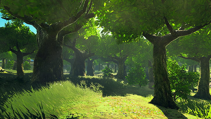
Instancing is an OpenGL technique to create multiple copies of the same geometry. It’s primary use is particle systems (dust, rain, explosions) and foilage (grass, trees, leaves) where massive amounts of the same geometry is created at the same time. The blades of grass in Breath of the Wild all have the same geometry and are instanced1 at different positions and orientations. We are going to use this technique to efficiently render sprites.
The code for this tutorial exists as a standalone example which can be found here.
OpenGL Setup
The first thing we have to do is to define the geometry that we will be instancing. This will be our sprite template.
var triangles = [18]float32{
    -0.5, -0.5, 0, // 0
    0.5, -0.5, 0,  // 1
    -0.5, 0.5, 0,  // 2
    -0.5, 0.5, 0,  // 3
    0.5, -0.5, 0,  // 4
    0.5, 0.5, 0,   // 5
}
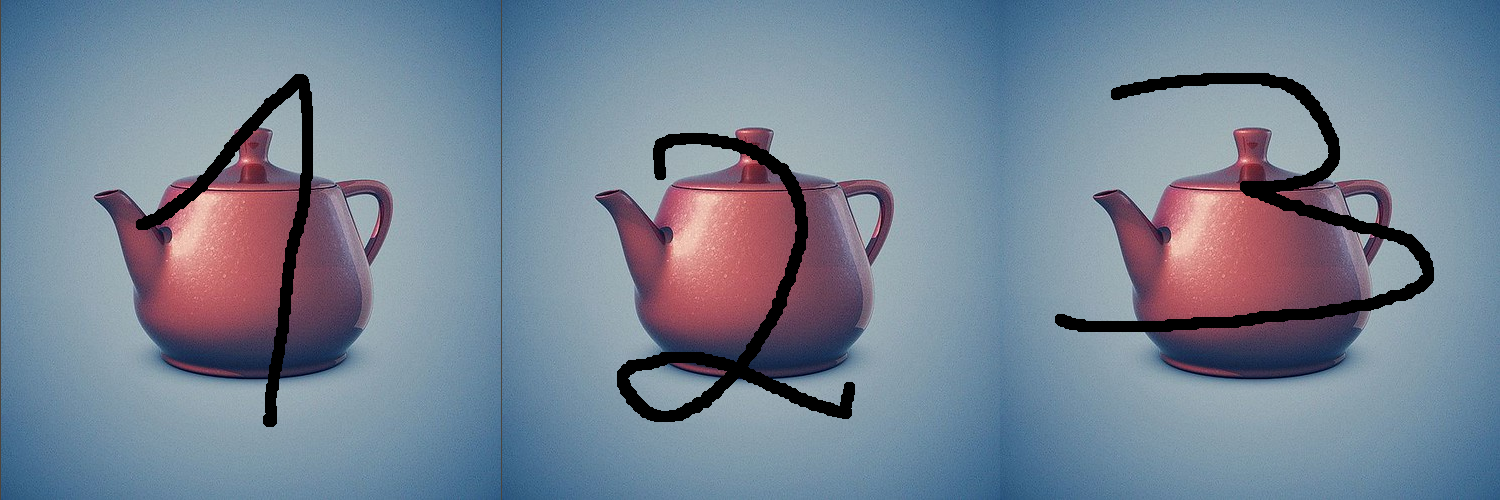
Every sprite will have this geometry and we will move, scale and rotate it to get any sprite that we need. For this tutorial, we are going to instantiate this sprite three times at different locations and with different uvs. Our locations will be the following:
var translations = [9]float32{
    -1.2, -1.1, 0, // sprite 1
    -0.8, 0, 0,    // sprite 2
    0.1, 0.1, 0,   // sprite 3
}
As a reminder, we use the term translation to mean movement and since our sprite’s initial position is moving by any amount sets the sprite’s location to that amount. In the above, we have one location for each sprite instead of one for each vertex (which is why we are using instancing!). For each sprite we also define a set of uv coordinates.
var uvs = [12]float32{
    0, 1, 0.33, 0,    // sprite 1
    0.33, 1, 0.66, 0, // sprite 2
    0.66, 1, 1, 0,    // sprite 3
}
In previous examples, we provided a uv coordinate for each vertex. Here, we provide a tuple of four values for each sprite. These values define a bounding box with the first two values representing the lower-left corner of the bounding box and the last two values representing the upper right corner. The Y values are inverted because in image coordinates the origin is at the top-left.

These uvs correspond to the spite sheet that we used in the animation tutorial.
Next, lets see how to copy our data to the GPU. The process for copying the vertex data is exactly the same as before. We create a vertex buffer and bind it to location 0 in our shader.
var vertexVbo uint32
gl.GenBuffers(1, &vertexVbo)
gl.BindBuffer(gl.ARRAY_BUFFER, vertexVbo)
gl.VertexAttribPointer(0, 3, gl.FLOAT, false, 0, nil)
gl.EnableVertexAttribArray(0)
gl.BufferData(gl.ARRAY_BUFFER, 4*len(triangles), gl.Ptr(&triangles[0]), gl.STATIC_DRAW)
The final line copies our triangle data to the GPU. As mentioned
earlier, we are going to create three sprites at different locations and
with different uvs. Before, this would require us to copy the
triangles array three times but here we only copy once.
This one triangle will be automatically replicated by the GPU.
The other two attributes we need to transfer to the GPU are the
sprite locations which live in the translations array and
the sprite uvs. The process for copying these is the same but with a
small addition.
var uvVbo, translateVbo uint32
gl.GenBuffers(1, &uvVbo)
gl.BindBuffer(gl.ARRAY_BUFFER, uvVbo)
gl.VertexAttribPointer(1, 4, gl.FLOAT, false, 0, nil)
gl.EnableVertexAttribArray(1)
gl.BufferData(gl.ARRAY_BUFFER, 4*len(uvs), gl.Ptr(&uvs[0]), gl.DYNAMIC_DRAW)
gl.VertexAttribDivisor(1, 1)

gl.GenBuffers(1, &translateVbo)
gl.BindBuffer(gl.ARRAY_BUFFER, translateVbo)
gl.VertexAttribPointer(2, 3, gl.FLOAT, false, 0, nil)
gl.EnableVertexAttribArray(2)
gl.BufferData(gl.ARRAY_BUFFER, 4*len(translations), gl.Ptr(&translations[0]), gl.DYNAMIC_DRAW)
gl.VertexAttribDivisor(2, 1)
The addition is the line gl.VertexAttribDivisor which
works like this. The first parameter is the attribute that we are
modifying, so we match it to the number in
EnableVertexAttribArray. In the example above, uvs are in
position 1 and translations are in position 2.
The second parameter is the interesting one. If we set that to zero,
it means that we are passing an attribute for each vertex
(which is the same as not calling VertexAttribDivisor). If
we set it to one, which is what we do here, it means that we are passing
an attribute for each instance of our geometry which for us is
the triangle pair that forms our sprite2. On
the shader side, the effect of this is that every vertex will get the
same value as if we where copying the attribute six times. To give a
concrete example, every one of the six vertices that make up our first
sprite will get translation=(-1.2, -1.1, 0) and
uv=(0, 1, 0.33, 0, 0).
To render this data, instead of calling gl.DrawArrays we
now call gl.DrawArraysInstanced:
gl.DrawArraysInstanced(gl.TRIANGLES, 0, 6, 3)This call instructs OpenGL to draw 3 copies of the
triangles array using 6 vertices (starting at index 0). The
final piece of code we need is a modification to our vertex shader.
Instanced Vertex Shader
The vertex shader runs once for every vertex of our geometry. Remember, our geometry for every sprite is this:
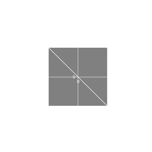
In the OpenGL setup code we passed a 4-tuple of uv coordinates for each instance of the geometry. So the first sprite, for example, would get the tuple . Every vertex of the sprite gets the same tuple so we need a way to extract the uv coordinate for the specific vertex out of this tuple. For the first sprite, these are the uvs that correspond to each vertex.
We could code this using if statements, and it would
look like this3:
if (vertex.x==0.5 && vertex.y==0.5) {
    textureCoords = vec2(uv.z, uv.w);
} else if (vertex.x==-0.5 && vertex.y==0.5){
    textureCoords = vec2(uv.x, uv.w);
}
//... two more cases
However, its better to avoid control statements (if, for, while etc)
when writing GLSL as it might hurt performance. Fortunately, many
control statements can be expressed as mathematical equations. The
following two statements cover all cases that we would code in an
if-else chain:
textureCoords.x = -(vertex.x-0.5)*uv.x  + (vertex.x+0.5)*uv.z;
textureCoords.y = -(vertex.y-0.5)*uv.y  + (vertex.y+0.5)*uv.w;
The trick here is that half of the equation always evaluates to zero
which lets it act as an if statement. Use the
mappings shown above and plug in some vertex values into the equations
to verify that they produce the correct uvs.
The calculation of uv values is the only change needed in our vertex shader. We don’t need to change anything in the fragment shader. The following is the complete vertex shader for this tutorial:
#version 410
layout (location=0) in vec3 vertex; // vertex position
layout (location=1) in vec4 uv; // per-vertex texture co-ords
layout (location=2) in vec3 translation;
out vec2 textureCoords;
// shader program
void main() {
textureCoords.x = -(vertex.x-0.5)*uv.x + (vertex.x+0.5)*uv.z;
textureCoords.y = -(vertex.y-0.5)*uv.y + (vertex.y+0.5)*uv.w;
gl_Position = vec4(vertex.x + translation.x, vertex.y + translation.y, vertex.z,1);
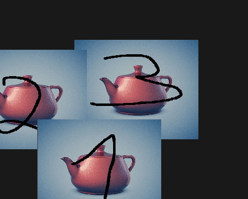
}If we run our code we get three instanced sprites:
In the previous tutorial we saw a complete vertex shader that allows for translation, rotation and scaling. Other than the uv calculation shown here, nothing changes in the shader. You can see the complete, instanced vertex shader used in AGL here.
This is an educated guess :).↩︎
We can also use values greater than one in
VertexAttribDivisorwhich causes attribute values to be replicated for multiple instances. A value of two, for example, makes it so that consecutive instances get the same attributes. We will not be using this feature.↩︎In reality we would never compare floating point numbers with an equality statement (
a==b) as it might fail in cases such0.99999999==1. Instead, we would use something of the formif(abs(a-b)<0.0000001).↩︎