Default Shader
In this tutorial we will create a complete shader that will serve as our engine’s default. Previous examples focused on the mechanisms of passing data from the main program to the shader. Here we will focus on the functionality of the shader itself.
In 3D games, shaders are crucial for setting the look of the game. Shaders are used to calculate the interaction between light sources, geometry, and materials in order to give the appearance of objects in the game. Shaders are also used to create various effects such as shadows, motion blur, particles and many more.
2D games typically don’t have to perform lighting calculations to show sprites and rely more on the artwork than on effects to set the look of the game. As a result, shaders for 2D games are less complicated. Having said that, for this tutorial we will need to use a few linear algebra concepts that may feel difficult if you haven’t had previous exposure to the subject. Feel free to gloss over any of the math in this tutorial. All of it is contained within the shader and will not affect your understanding of the rest of the game engine.
Vertex Shader
Our vertex shader is responsible for setting the position, rotation and size of our sprite. In previous examples we set the position and size of our sprites manually by changing the vertex coordinates of the each triangle. This is cumbersome and inefficient so we will switch to a different approach. From now on we will always send a fixed set of sprite vertices to the shader which we will call our sprite template.
// 2   3-5
// |\   \|
// 0-1   4
var spriteTemplate = [18]float32{
    -0.5, -0.5, 0, // 0
    0.5, -0.5, 0,  // 1
    -0.5, 0.5, 0,  // 2
    -0.5, 0.5, 0,  // 3
    0.5, -0.5, 0,  // 4
    0.5, 0.5, 0,   // 5
}
These vertices form the following two triangles.
Every sprite in the game will be instantiated with the above geometry. Then, we will move, scale and rotate these template vertices to create any sprite that we need. This will happen on the GPU using our vertex shader. To do that, in addition to the above vertices, we also send the information to move, scale and rotate the sprite as separate shader attributes. Our shader’s layout parameters will be the following:
layout (location=0) in vec3 vertex;      // vertex position
layout (location=1) in vec2 uv;          // per-vertex texture co-ords
layout (location=2) in vec4 color;       // passed to the fragment shader
layout (location=3) in vec3 translation; // sets the position of the sprite
layout (location=4) in vec3 rotation;    // rotation of the sprite (in all three axis)
layout (location=5) in vec2 scale;       // size of the sprite
We already saw what the vertex and uv
parameters do in previous examples. We can also ignore the
color parameter as it doesn’t affect the vertex shader at
all. We just pass it along to the fragment shader. The parameters
translation, rotation and scale
are crucial to the operation of our vertex shader. Lets examine each
parameter individually.
Translation
The translation parameter is used to move our sprite.
Moving a sprite is straightforward. We just add translation
to the vertex.
position = vertex + translation;
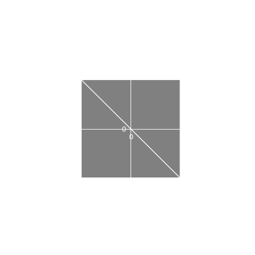
gl_Position = vec4(position,1);This translates (fancy term for moves) the sprite by
translation units. gl_Position is a vec41 so we append a 1 at the end. We
purposely set the vertices in our sprite template to be around the
origin
so adding translation to our vertices has the effect of
setting the sprite’s position. Here is an example of a translation in
action.
![]()
All vertices are moved by 1.5 units to the right and by 1 units down.
Scale
Scale affects the size of the sprite. By default, the sprite has a size of one unit which takes up a quarter of the screen. Scaling by a fraction in the range makes the sprite smaller and scaling by a number greater than one makes it bigger. Here we scale the object by a factor of two on the X and Y dimensions which makes the sprite 4 times bigger.
Notice that our scale parameter is a vec2.
This is because we can scale the X and Y parameters of our sprite
independently which lets us create sprites that are not square. In the
first example below, we scale by
which stretches the object horizontally leaving the Y axis unchanged.
It’s a common mistake to scale by zero when the intent is to leave a
dimension unchanged. In the second example we scale by
.
To apply scale, we multiply our vertex position with the
scale parameter.
gl_Position = vec4(vertex.x*scale.x, vertex.y*scale.y, vertex.z, 1) + translation;Notice that we add translation after we scale
our vertex. If we added translation and then scaled, the
translation amount would be scaled as well and we would have ended with
a sprite at the wrong position and with the wrong size.
Rotation
Rotating our sprite is done by moving the vertices of the sprite in a circular pattern. For simplicity, lets assume we are only rotating around the viewing direction which for us is the Z axis. Rotating around the Z axis means that the Z parameter stays the same and X and Y change. This produces rotations like this:
Rotating a vertex with coordinates around the Z axis by degrees is achieved with this formula:
For these equations to make intuitive sense, we must discuss polar coordinates and do a little derivation so we will skip it for now. For the mathematically interested, see this very nice explanation. If we convert these equations to code, we get:
position = vec3(vertex.x*cos(t)-vertex.y*sin(t), vertex.x*sin(t)+vertex.y*cos(t), vertex.z);This is great if we just need to rotate our sprite, but what happens if we want to mix rotation with translation and scaling as well? In such a case we need to be careful to apply our operations in the correct order.
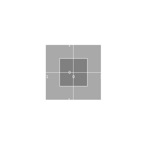
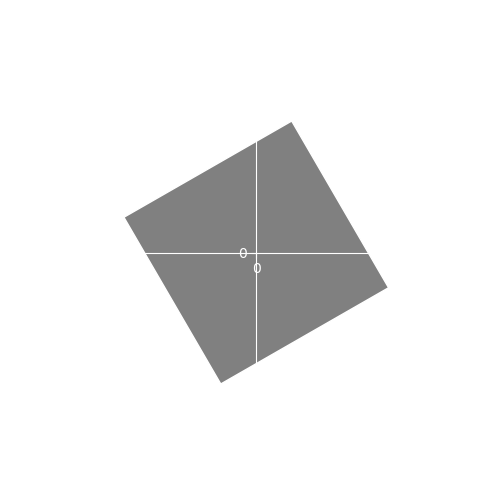
As an example, lets examine a case where we have to rotate and translate at the same time. Lets say we want to rotate our sprite 45 degrees and move it one unit to the right. If we apply the rotation and then translate we get:
![]()
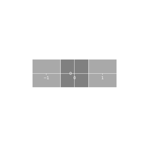
Which is what we expect. But, if we translate and then rotate we then get:
![]()
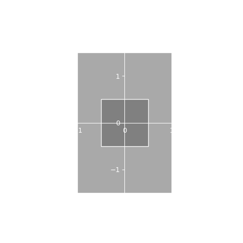
Which is not what we wanted. A way to think about this is that rotation always happens around the origin point . If we rotate first, while the sprite’s center is at , the sprite rotates on it’s center. Translation then moves the already rotated sprite to and we get the expected result. If we translate first, the sprite’s center becomes but the center of rotation is still which causes the sprite to orbit . If we increase the translation to 2 units this becomes more obvious:
![]()
So, just as with translation and scale, the order of operation matters. If all of this sounds confusing, just remember that we apply transformations in this order: scale first, rotation second and translation third.
Rotation on the X and Y Axis
At first it might seem that we don’t need these rotations for 2D games but they are useful for at least one thing and that is flipping sprites. By doing a half circle (180 degree) rotation on the Y axis we can reverse the left/right direction that our sprite faces. Similarly, we rotate 180 degrees on the X axis to flip our sprite upside down. This allows us to only have artwork for two of the four common directions (up, down, left and right) and flip the sprite when the sprite needs to face the other way. Applying the rotations to the X and Y axis is similar to the rotation we coded for the Z axis so we won’t show it here.
With rotation done, our vertex shader is finished but before we move to the fragment shader, lets look at another way to do transformations.
Matrix
A matrix is a mathematical object that lets us apply transformations, such as translation, rotation and scaling, to vectors or in our case vertices. To apply a matrix transformation, we multiply the matrix with the vertex.
OpenGL handles the actual multiplication for us so don’t worry about coding this. All we need to do is create the matrices.
Next, lets look at the matrices used to do the transformations we saw before: translation, rotation and scale.
Translation Matrix
As we saw before, translation is just adding a vector to our vertex. We can do addition using the following matrix.
Notice that the matrix is
so to apply it to our vec3 vertex we must add an extra
dimension and set it to 1. This is why the gl_Position
built-in variable in GLSL is of type vec4. If we multiply
the above matrix and our vertex, we get translation:
In code, x,y,z would be vertex.xyz and
a,b,c would be translation.xyz. Why we go to
all this trouble just to add two vectors together will be revealed in a
bit!
Scale Matrix
The scaling matrix is the following.
Try the matrix multiplication on your own to confirm that the matrix
works as advertised. This is the general form of the matrix for 3D but
in our case c will always equal 1 as our sprites don’t have
depth.
Rotation Matrices
For rotation we need to define one matrix for each axis of rotation. The following matrices define the X, Y and Z rotations respectively:
To understand what these do, let’s examine the matrix for the rotation around Z.
We can see that this matrix multiplication produces the formula we used previously when we coded rotation without matrices.
The matrices for X and Y work similarly. It would be good practice to do one of the multiplications manually and verify it works.
Combining Matrix Transforms
We now have 5 matrices (translation, scale and three rotations) that when combined will allow us to have a complete system to control our sprite. Fortunately, combining matrices is very easy, we just multiply them. If is the translation matrix, is the scale matrix and , , and are the rotation matrices, our complete transform, , is given by:
The order of multiplication is very important as we will see later. We can apply all transforms at once by multiplying our vertex with CT.
This is one of the main benefits of using matrices to do transformations. Any number of transformations can be combined together using matrix multiplication and applied to vertices with one matrix-vertex multiplication.
Order of Multiplication
We saw previously that the order in which we apply our transforms matters. The same is true when transforms are expressed as matrices. Let’s use translation and scaling as an example. Lets say we multiply the translation and scale matrices in this order.
The resulting transformation matrix is wrong as the translation is also scaled. If we reverse the order we get:
Which is the correct matrix. It’s a good idea to pause here and try both matrices with some real numbers.
Matrices in Shader Code
We want to create matrices to express the transforms that will be applied to our vertex. In the beginning of this tutorial we defined the following shader attributes. These will be used as input to create our transformation matrices.
layout (location=0) in vec3 vertex;      // vertex position
// uv and color attributes omitted
layout (location=3) in vec3 translation; // sets the position of the sprite
layout (location=4) in vec3 rotation;    // rotation of the sprite (in all three axis)
layout (location=5) in vec2 scale;       // size of the sprite
Matrices are natively supported in GLSL. Let’s see how we define a matrix, using the scale matrix as an example.
mat4 scale_mat = mat4(1.0);
scale_mat[0][0] = scale.x;
scale_mat[1][1] = scale.y;
In the above, mat4 defines a
matrix. The code mat4(1.0) initializes a matrix with zeroes
and sets the diagonal to 1.0. This creates the identity
matrix which is the following2:
GLSL matrices are accessed like 2D C arrays which is what we do in the other two lines to set up our scale matrix. The translation matrix is created in a similar manner but instead of setting matrix elements one by one, we replace the whole fourth column3 with the required values.
mat4 translate_mat = mat4(1.0);
translate_mat[3] = vec4(translation, 1); // same as vec4(translation.x, translation.y, translation.z, 1)
Rotation matrices are also initialized as identity matrices. We then set individual matrix elements to the desired value.
mat4 rotate_mat_x = mat4(1.0);
float c = cos(rotation.x);
float s = sin(rotation.x);
rotate_mat_x[1][1] = c;
rotate_mat_x[2][2] = c;
rotate_mat_x[1][2] = -s;
rotate_mat_x[2][1] = s;

mat4 rotate_mat_y = mat4(1.0);
c = cos(rotation.y);
s = sin(rotation.y);
rotate_mat_y[0][0] = c;
rotate_mat_y[2][2] = c;
rotate_mat_y[0][2] = s;
rotate_mat_y[2][0] = -s;

mat4 rotate_mat_z = mat4(1.0);
c = cos(rotation.z);
s = sin(rotation.z);
rotate_mat_z[0][0] = c;
rotate_mat_z[1][1] = c;
rotate_mat_z[0][1] = -s;
rotate_mat_z[1][0] = s;
Matrices are combined using matrix multiplication which in GLSL is
conveniently done with the * operator. Matrix-vector
multiplication is also done with * and our complete vertex
transform process can be expressed with a single line of code:
gl_Position = translate_mat * rotate_mat_x * rotate_mat_y * rotate_mat_z * scale_mat * vec4(vertex, 1.0); Fragment Shader
After all this work in the vertex shader, you will be relieved to see that the fragment shader is very simple.
uniform sampler2D tex;
in vec2 texCoords;
in vec4 vertColor;
out vec4 frag_colour;

void main() {
    vec4 texel = texture(tex, texCoords);
    if(texel.a < 0.5) discard;
    frag_colour = texel * vertColor ;
}
We get the texture coordinates from the vertex shader and use them to
access our atlas texture to get our sprite’s texture value. The texture
is multiplied by the vertex color (vertColor). This lets us
apply a very simple color effect on our sprite. If
vertColor is white then our sprite will appear as it is on
the sprite atlas. Setting vertColor to shades of gray will
darken the sprite and setting it to a color other than gray will tint
it.
The line if(texel.a < 0.5) discard; completely
discards the current fragment if the opacity value is less than
.
This is an efficient way to enable transparency under the condition that
a pixel can be either fully transparent or completely opaque. If we want
partial transparency we can remove that line from the shader but that
comes with a downside. For partial transparency to work, opaque sprites
must be drawn before transparent ones and the user needs to ensure this
ordering manually which is very cumbersome 4.
Attribute Duplication
Shader parameters are passed for each vertex. However, our transform parameters, translation, rotation and scale, apply to the whole sprite. We have 6 vertices per sprite which means we are copying these parameters 5 times for no reason. On top of that, because we are using a sprite template, we copy the same vertex coordinates for every sprite that we want to render, even though these never change which is sub-optimal.
On a modern computer these inefficiencies don’t really matter unless we have to render many thousands of sprites each frame and we shouldn’t optimize prematurely5. On the other hand, copying sprite attributes is a big part of what our rendering system does so an optimization would not be a waste of time. The way to optimize this is interesting and not hard to do so we will go over it in the next tutorial.
This is because it is in homogeneous coordinates. See https://en.wikipedia.org/wiki/Homogeneous_coordinates for more.↩︎
This might seem weird, as we could expect
mat4(1.0)to initialize the whole matrix to 1 but identity matrices are a more useful initialization option.↩︎In GLSL, matrices are stored in column-major order, see https://en.wikipedia.org/wiki/Row-_and_column-major_order.↩︎
AGL has a mechanism to make this easier called render order.↩︎
“Premature optimization is the root of all evil” - Donald Knuth↩︎